Discontinuous versus Continuous
A discontinuous medium is distinguished from a continuous one by the existence of contacts or interfaces between the discrete bodies that make up the system. Discontinuum methods can be categorized both by the way they represent contacts and by the way they represent the discrete bodies in the numerical formulation.
Solution Cycle
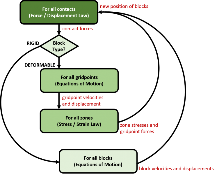
In the distinct element method, a rock mass is represented as an assembly of discrete blocks. Joints are viewed as interfaces between distinct bodies (i.e., the discontinuity is treated as a boundary condition). The contact forces and displacements at the interfaces of a stressed assembly of blocks are found through a series of calculations that trace the movements of the blocks. Movements result from the propagation through the block system of disturbances caused by applied loads or body forces. This is a dynamic process in which the speed of propagation depends on the physical properties of the discrete system.
The dynamic behavior is represented numerically by a timestepping algorithm in which the size of the timestep is limited by the assumption that velocities and accelerations are constant within the timestep. The distinct element method is based on the concept that the timestep is sufficiently small enough that during a single step, disturbances cannot propagate between one discrete element and its immediate neighbors. This corresponds to the fact that there is a limited speed at which information can be transmitted in any physical medium. The solution scheme is identical to that used by the explicit finite-difference method for continuum analysis. The timestep restriction applies to both contacts and blocks. For rigid blocks, the block mass and interface stiffness between blocks define the timestep limitation; for deformable blocks, the zone size is used, and the stiffness of the system includes contributions from both the intact rock modulus and the stiffness at the contacts.
The calculations performed in the distinct element method alternate between application of a force-displacement law at all contacts and Newton’s second law at all blocks. The force-displacement law is used to find contact forces from known (and fixed) displacements. Newton’s second law gives the motion of the blocks resulting from the known (and fixed) forces acting on them. If the blocks are deformable, motion is calculated at the gridpoints of the triangular finite-strain elements within the blocks. Then, the application of the block-material constitutive relations gives new stresses within the elements.

What is the difference between distinct element and discrete element?
Many finite element, boundary element and Lagrangian finite difference programs have interface elements or “slide lines” that enable them to model a discontinuous material to some extent. However, their formulation is usually restricted in one or more of the following ways:
- The logic may break down when many intersecting interfaces are used;
- There may not be an automatic scheme for recognizing new contacts; and
- The formulation may be limited to small displacements and/or rotation (such programs are usually adapted from existing continuum programs).
The name “discrete element method” applies to a computer program only if it:
- Allows finite displacements and rotations of discrete bodies, including complete detachment; and
- Recognizes new contacts automatically as the calculation progresses.
Without the first attribute, the model cannot reproduce some important mechanisms in a discontinuous medium; without the second, the model is limited to small numbers of bodies for which the interactions are known in advance. The term “distinct element method” was coined by Cundall and Strack (1979) to refer to the particular discrete element scheme that uses deformable contacts and an explicit, time-domain solution of the original equations of motion (not the transformed, modal equations).
