
An important aspect of geomechanical analysis and design is the use of structural support to stabilize a soil or rock mass. The term support describes engineered materials used to restrict displacements in the immediate vicinity of an opening. 3DEC support elements include:
- Beam Structural Elements
- Cable Structural Elements
- Pile Structural Elements
- Shell Structural Elements
- Geogrid Structural Elements
- Liner Structural Elements
These elements are the same elements used in FLAC3D. There are also two 3DEC-specific structural elements, specifically designed to resist shearing on joints:
- Local Reinforcement
- Hybrid Bolts
The local reinforcement elements provide a simple way to simulate a bolt that resists joint movement. Springs are added at each joint-bolt intersection to resist shear and tensile joint motion. Hybrid bolts take this a step further as described below.
The 3DEC-specific reinforcement types are described separately, below. In all cases, the commands necessary to define the structure(s) are quite simple, but they invoke a very powerful and flexible structural logic. This logic is developed with the same finite-difference algorithms as the rest of the code, allowing the structure to accommodate large displacements, and to be applied for dynamic (option) as well as static analysis.
Hybrid Bolts
The hybrid bolt is a one-dimensional reinforcement element developed for 3DEC that features a more realistic resistance to fracture shear displacement designed to simulate a rockbolt in a jointed rock mass. The hybrid bolt consists of two components: a ‘cable’ with a specified tensile strength and stiffness that resists shear along its length (i.e. pull-out), and a ‘dowel’ segment that resists lateral shear where the bolt crosses a rock joint. The dowel really represents a set of complex mechanical effects, including bending of the steel bolt, crushing of the grout, crushing of the host rock etc. In 3DEC, this is simply represented by a spring resisting shear on the joint, but by careful calibration of stiffness and strength parameters, the three stages of load response (elastic, yield and plastic stages) typically observed in laboratory tests can be obtained.
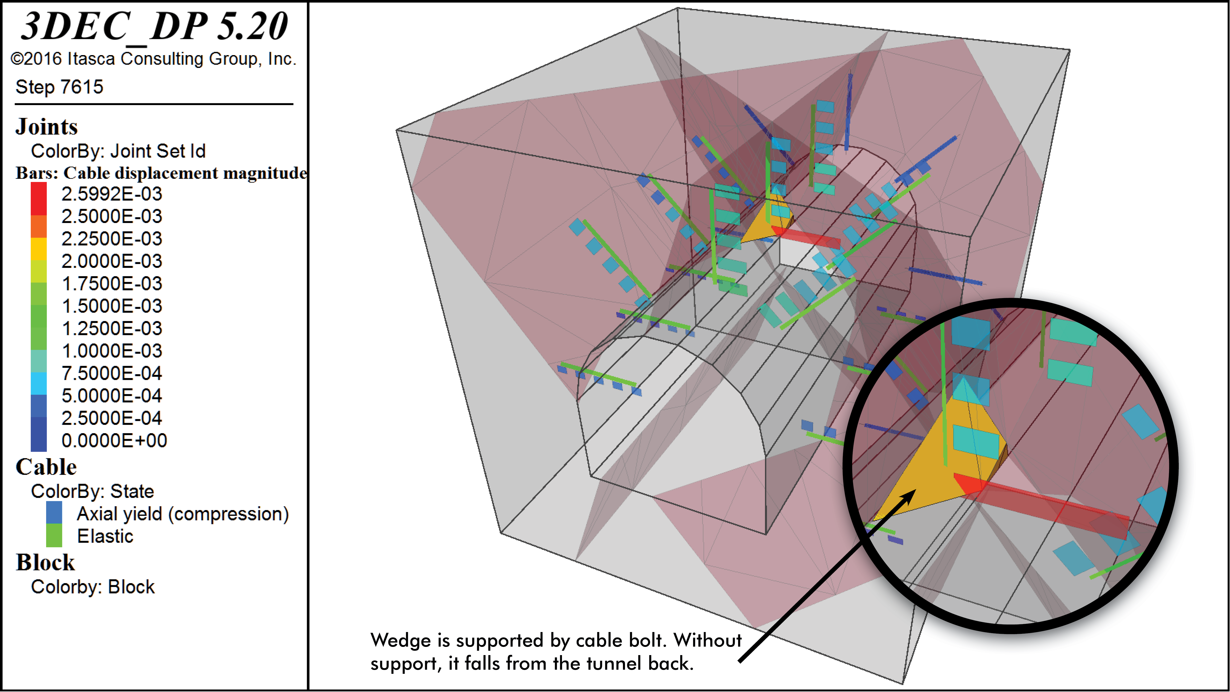
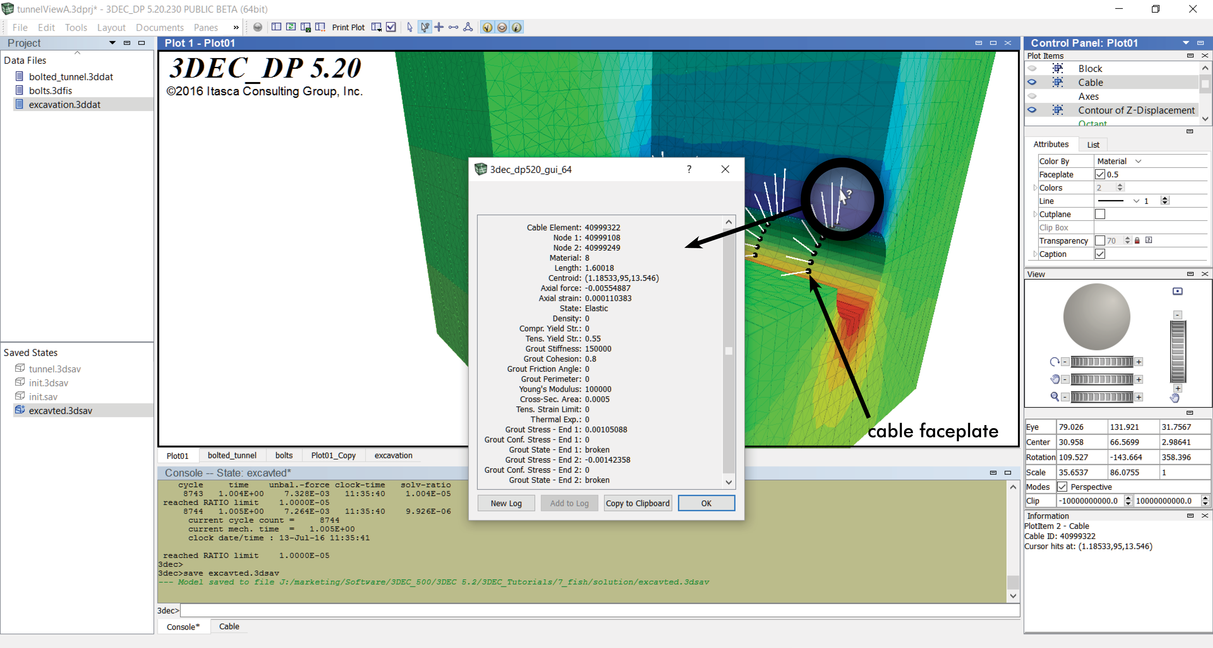
The following video shows the response of cable ground support around a tunnel. Although the material is excavated instantaneously to represent the tunnel void, the tunnel boundary is actually relaxed gradually to correctly simulate tunneling behavior.