Contents
Why Use FLAC3D for Dynamic Analysis?
Full Non-linear Solution in Time Domain
Customize Physics Through the Use of FISH or C++ Module
Why Use FLAC3D for Dynamic Analysis?
FLAC3D is especially useful for performing dynamic analyses. This page provides a brief overview of some of the features that make FLAC3D ideal for dynamic analysis.
Full Non-linear Solution in Time Domain
FLAC3D will provide a fully non-linear and path-dependent solution in time domain. FLAC3D uses the full equations of motion in its solution process. For static analysis, additional damping and mass scaling are introduced to facilitate the process of approaching the static equilibrium. For a dynamic solution, FLAC3D uses real grid-point masses and physically realistic damping. In short, for most purposes dynamic versus static is simply a small variation in the solution process.
The non-linearity and path-dependency of the stress-strain response is determined based on the constitutive law used at each zone. For a comprehensive constitutive law, modulus degradation and variation in damping due to changes in strain are inherent to the constitutive law. For simpler constitutive laws however, use of hysteretic damping and/or Rayleigh damping is advised.
The approach utilized by FLAC3D for obtaining a non-linear path-dependent solution in the time domain contrasts with the equivalent-linear methods commonly used in earthquake engineering, where response is obtained in frequency domain and the effects of any non-linearities are included in an incremental fashion. For more information about the differences and similarities of the two methods see the “Dynamic Analysis” section of the FLAC3D Manual.
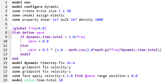
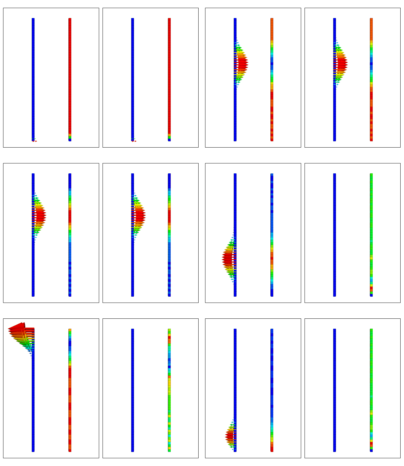
The sample code included below models 1-D wave propagation of a shear wave generated at the bottom of the model. The excitation is comprised of a single frequency pulse with a reflective boundary at the bottom and a free top boundary. The simulation is undamped, and none of the boundaries are absorbent, so the wave will propagate indefinitely.
The second plot shows the same model, but with a quiet boundary defined at the bottom of the model. Note that the wave travels upward, reflects back into the model from the free surface, returns to the bottom boundary and then vanishes.
Do it yourself: The commands below can be run in the demo version of FLAC3D 6.0. Use the command model solve time-total 10 to run the analysis for 10 seconds of model time. Continue for any given number of seconds.
Built-in P2PSand Dynamic/Liquefaction Constitutive Model
Itasca is pleased to announce P2PSand (Practical Two-Surface Plasticity model for Sands), our new practice-friendly 3D liquefaction constitutive model for FLAC3D based on the DM04 (Sanisand) model (Dafalias & Manzari, 2004). By revising some formula without destroying the conciseness of the original DM04 (Sanisand) model, the modifications improve the comparative results between model simulations and various laboratory and field observations with various initial and loading conditions. In addition, Itasca's new liquefaction model embraces an easier and more practical calibration procedure in terms of in-situ data, instead of experimental data, greatly reducing the laboriousness of calibration.
More information about the P2PSand model.
Coupling With Ground Water
Dynamic analysis in FLAC3D can include the effect of ground water by configuring the analysis for ground water calculations, and defining groundwater characteristics. Whether or not the actual flow of fluid is included in calculations is up to user. Most often, flow is not active during short bursts of dynamic loading (such as a 60 second earthquake, for example), since that is too short a time for any significant flow to occur. Even if flow is not considered, volumetric changes of the zones will still affect the changes of pore pressure.
Constitutive laws in FLAC3D are defined in terms of effective stress, to allow generation and dissipation of pore pressures during and after dynamic excitation.
The ability of cohesionless soils to densify when submitted to static or cyclic loading causes the decrease of effective stress and this leads to liquefaction. Coupling with groundwater provides ability to model liquefaction. More information on liquefaction, built-in constitutive models which allow liquefaction modeling, as well as other constitutive models available in literature and available as FLAC3D plug-ins can be found in the “Dynamic Pore-Pressure Generation” topic of the “Dynamic Analysis" section in the FLAC3D Manual.
The hydrodynamic effects of free standing water in the reservoir can be incorporated by modeling water directly using zones, or by use of the zone face westergaard command which adjusts the mass of the face gridpoints and estimates the magnitude of the hydrodynamic forces. For more information, see the FLAC3D 6.0 command documentation.
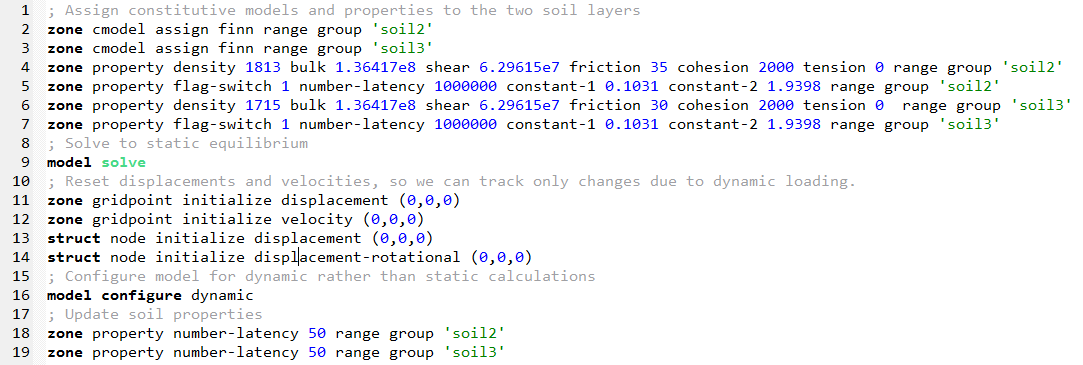
The commands below assigns the FINN constitutive model to selected regions in the model, defines material properties for static analysis, and subsequently changes one property (latency) for a dynamic analysis.
Soil-Structure Interaction
Structural elements can be incorporated into the model, and soil-structure interaction accounted for. Several types of structural elements are available in FLAC3D: beams, cables, piles, shells, geogrids, and liners. All structural elements can be used in both dynamic and static analysis.
The dynamic model can be comprised of structural elements only, or, more commonly, structural elements embedded or connected to the grid.
Structural behavior is defined by a set of properties corresponding to the type of the structural element, and properties of the interface between the structural element and the grid. For more information, see the "Structural Elements" section of the FLAC3D Manual.
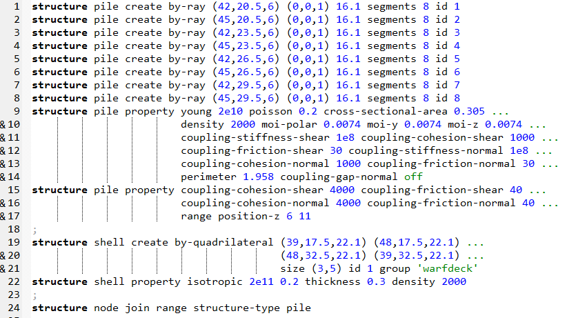
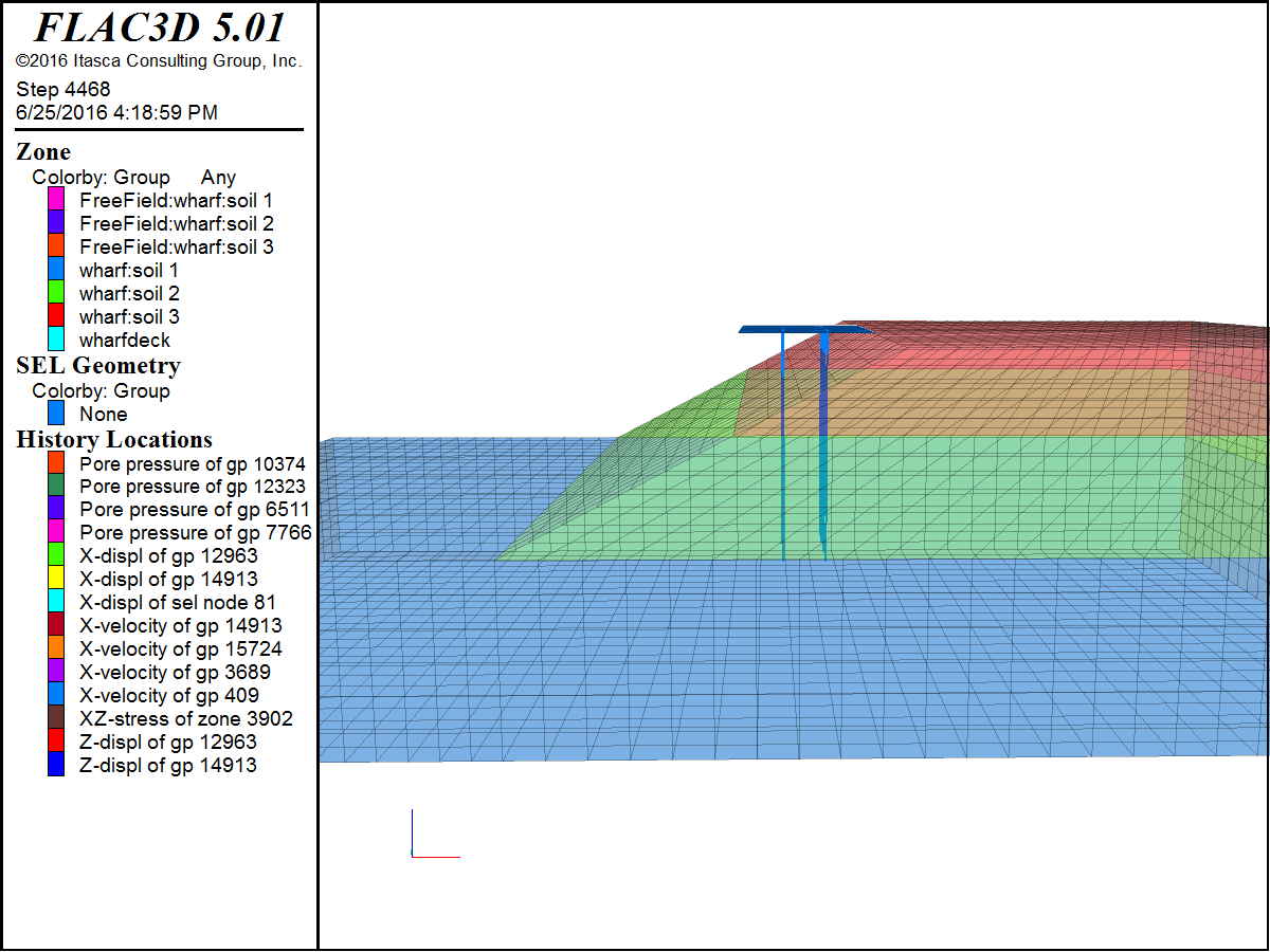
The wharf example below features two types of structural elements, piles and shells. Ground water is included in the model and pore pressure generation caused by earthquake loading is modeled using the FINN constitutive law. The whole model can be found in the FLAC3D documentation; what is presented here is sample code defining structural elements and the properties of the structure and the interface between the structure and the grid.
Customize Physics Through the Use of FISH or C++ Module
FISH is a built-in scripting language that gives user control of almost every aspect of program operation, including operation in dynamic mode. Enhancement or modification of the physics, or addition of user defined variables relevant to dynamic analysis is available through the use of FISH. In the FLAC3D Manual see “Scripting FISH in FLAC3D” and “User Defined Models in FLAC3D” for more information.
Powerful and Easy Preprocessing of Input Signals
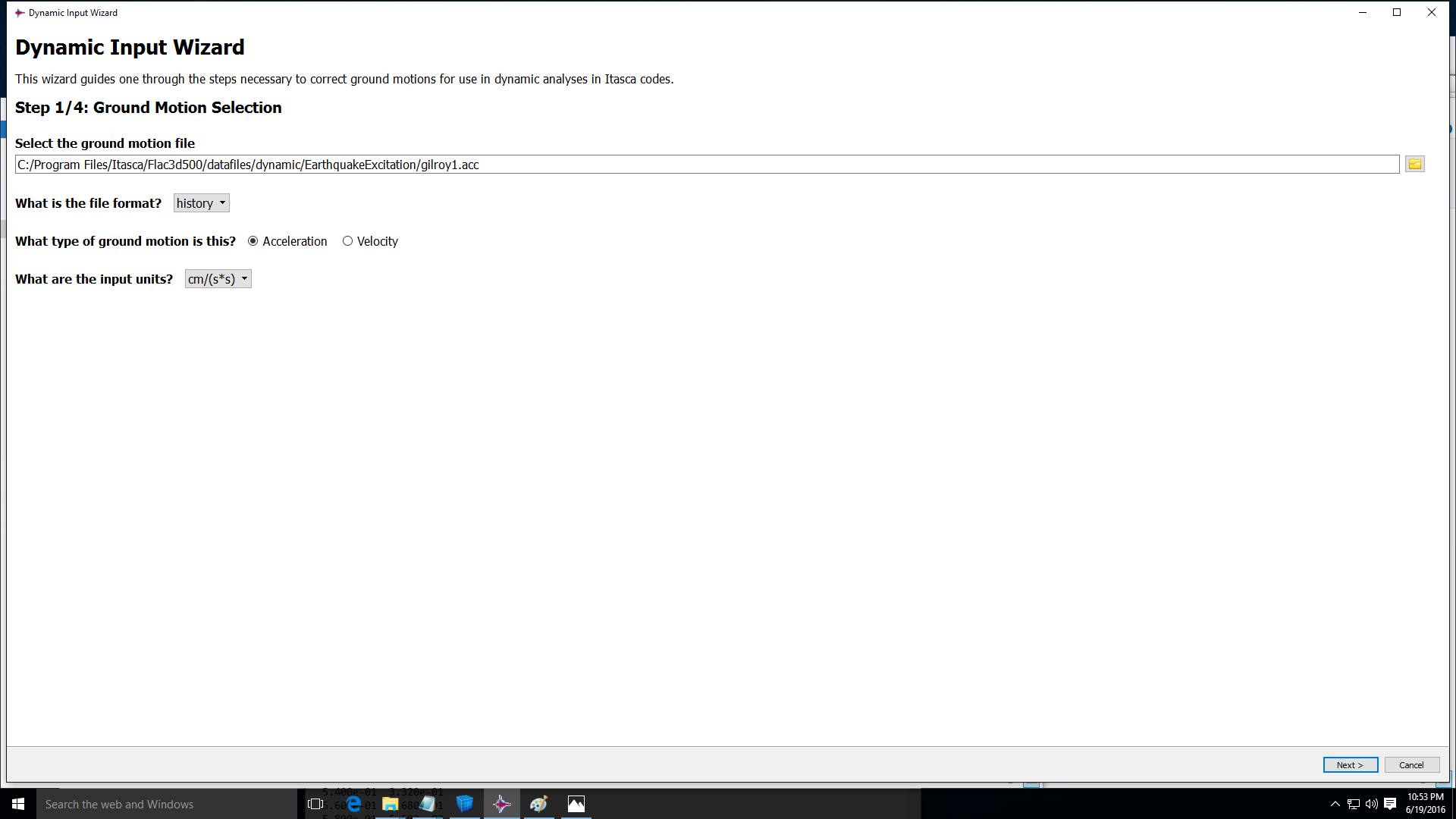
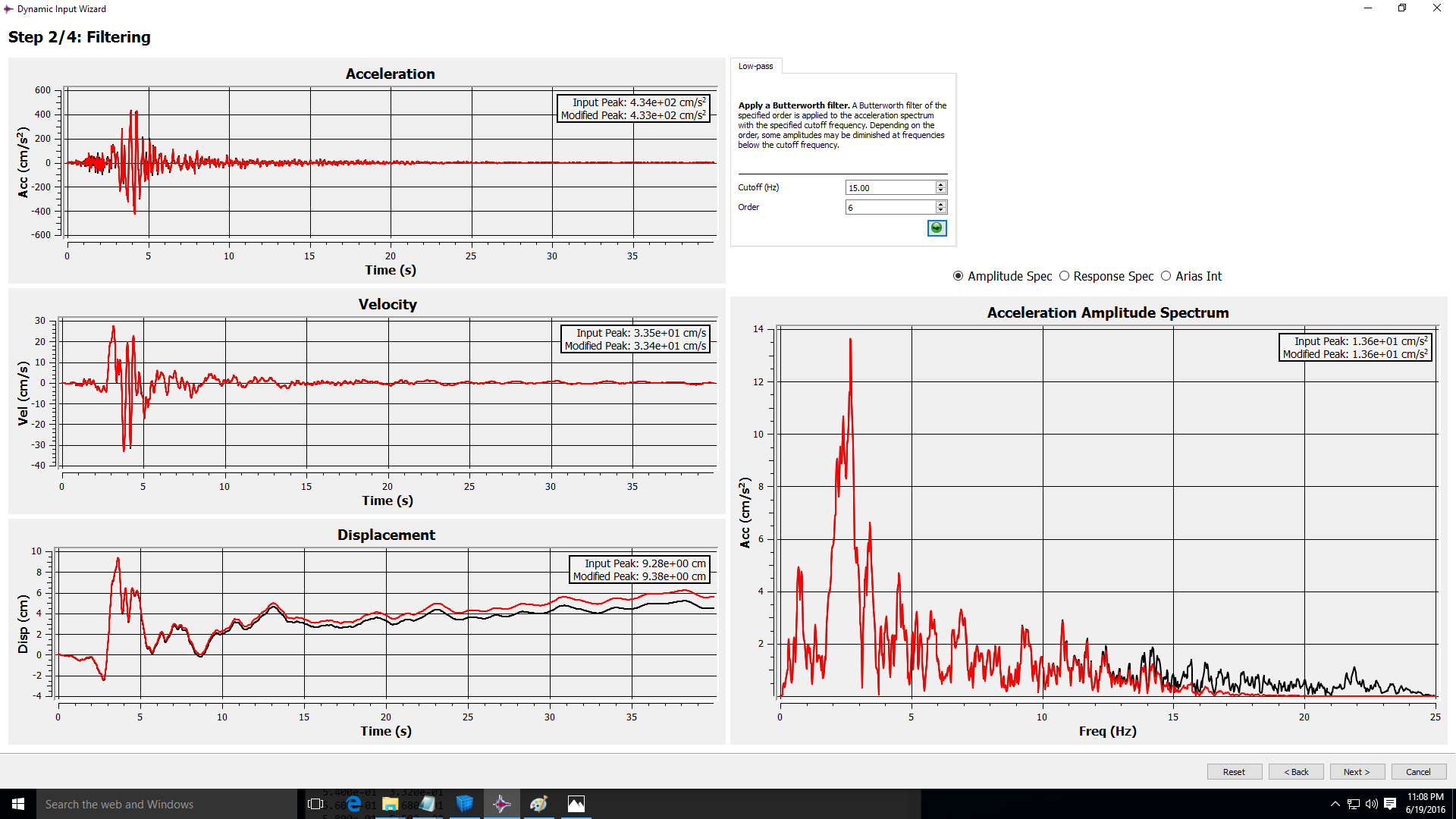
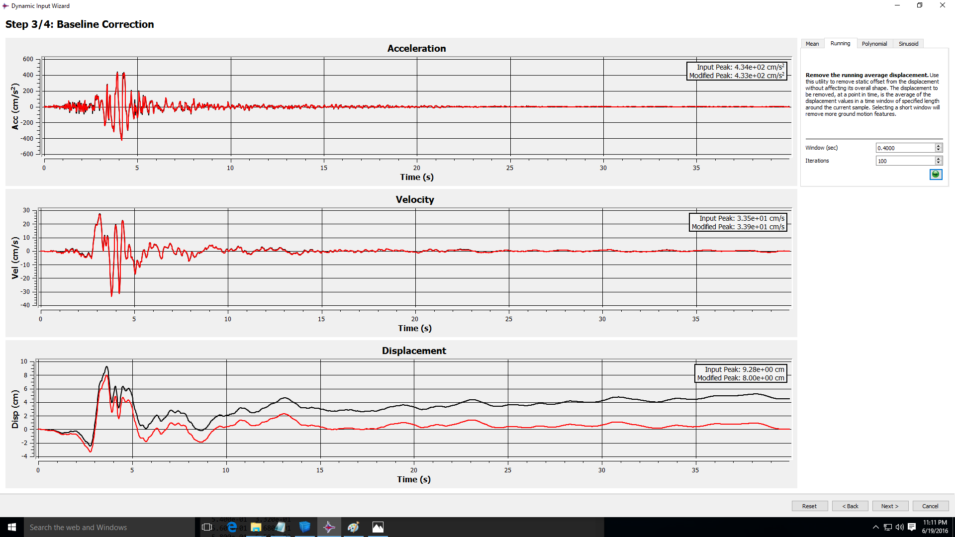
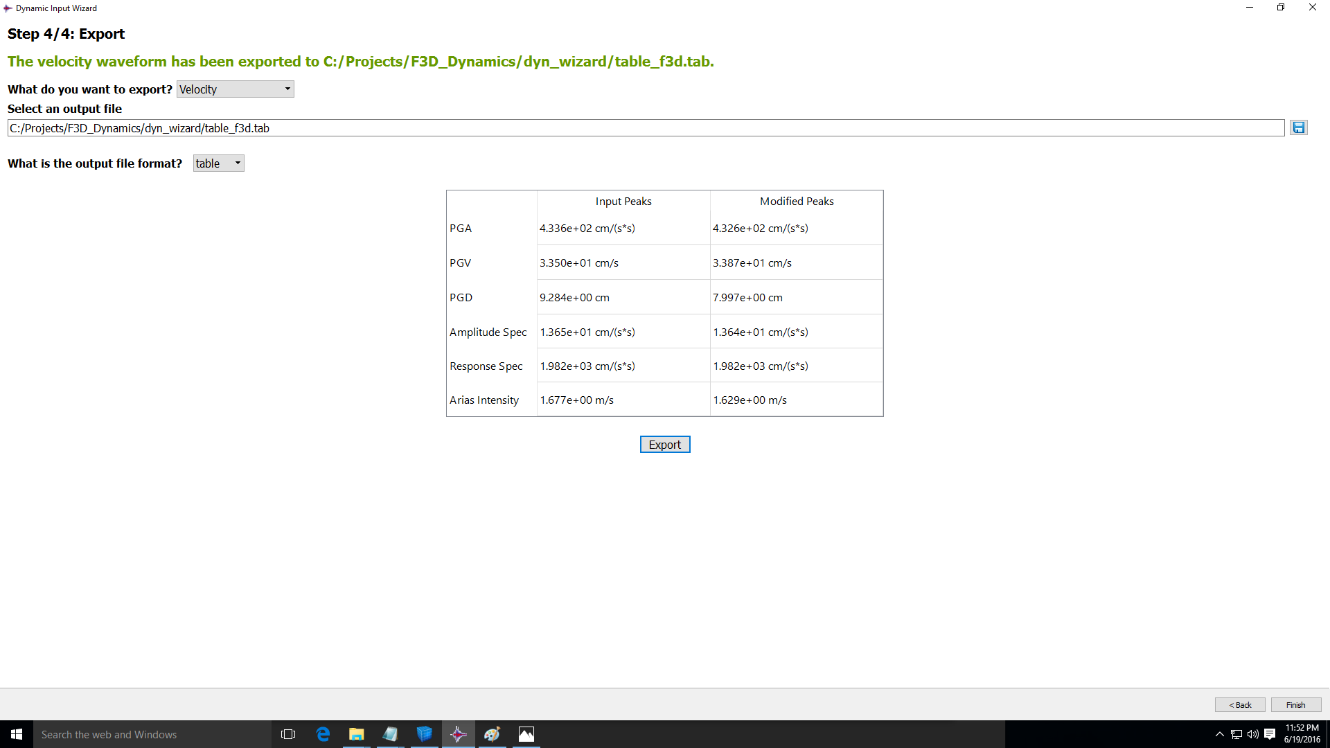
The Dynamic Wizard is a pre-processing tool that includes the following functionality:
- Importing ground motion data (velocity or acceleration) from a history, table or PEER file.
- Filtering ground motion data to remove high-frequency components with a specified cut-off frequency.
- Adding a baseline correction for velocity or displacement drift by removing the mean acceleration, the running average displacement, a polynomial fit displacement or a low-frequency sine function from the acceleration or velocity.
- Export processed data, such as acceleration, velocity, displacement, amplitude spectrum, response spectrum, or Arias intensity as a FLAC3D table.
- Signals recorded during FLAC3D dynamic analysis can be processed by the Dynamic Wizard (frequency content found, response spectrum,…)
Easy Movie Creation
In FLAC3D 6.0, results files can be easily exported at regular intervals during the dynamic analysis. The user can choose which information to include. These files are much faster and smaller than full save files, which contain all the information needed to restart and continue an analysis.
In addition, a new Wizard allows you to choose a sequence of results (or save files) and automatically generate a sequence of frames from a set of selected plots. These frames can be easily assembled into an animated movie using any of many available third-party software.
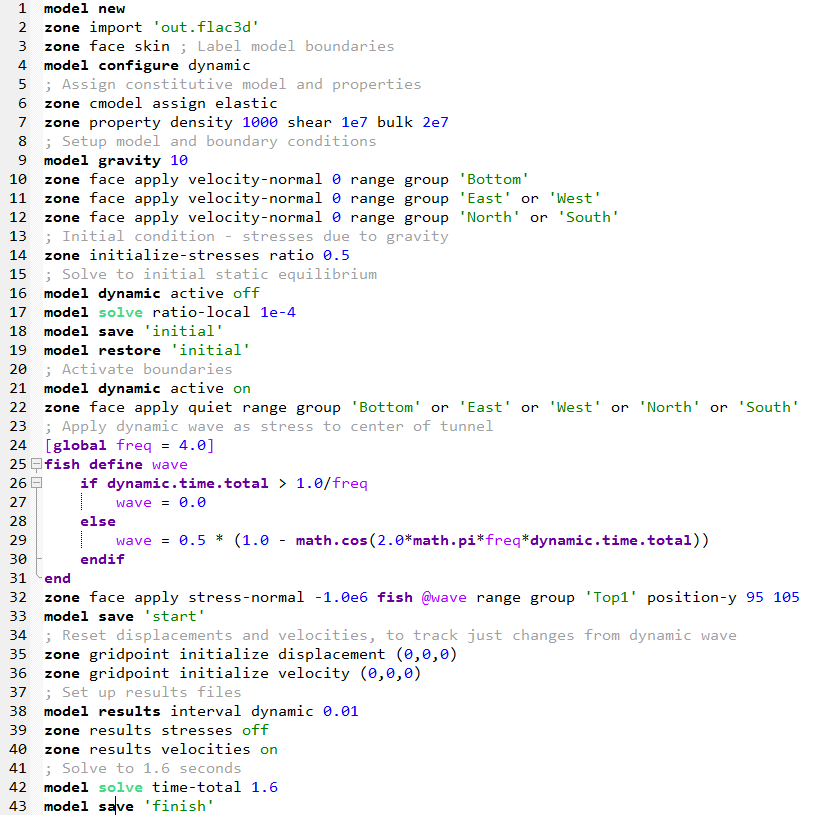
The commands below indicate that a results file should be saved every 0.01 seconds of dynamic time. It removes stress information (present by default) and adds velocity vectors to the displacement vectors that are also present by default.

After the dynamic analysis is performed, the "Generate Movie Frames" wizard is used to generate a series of images that are merged into a gif file, depicting displacement and velocity iso-surfaces representing propagation of the pressure wave created by the explosion in the middle of the tunnel. Note that absorbing boundaries at the bottom and sides of the model absorb the energy of the incoming waves, and there are no reflections back in to the model.
The full data file used to generate this movie is presented below:
